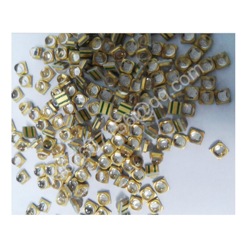
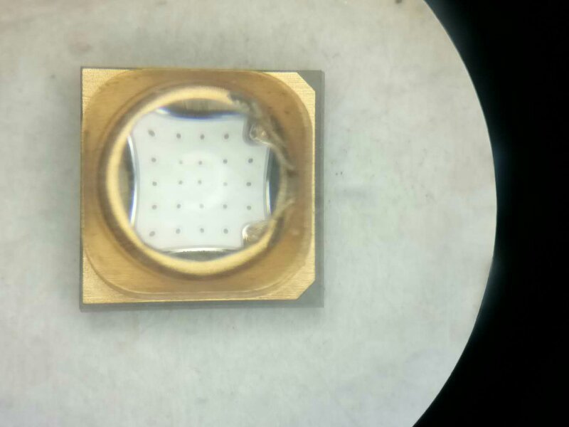
UV 365 nm hard quartz glass lenses; minimum beam angles of 30° and 60°; 3535 violet light lamps available in 365 nm, 395 nm and 405 nm wavelength bands
Precautions for Use
Product Storage Conditions
1. The product must be stored in a dry environment with a relative humidity of less than 30%, at a temperature of 5–30 °C.
2. Avoid damaging the vacuum-sealed bags with external force, to prevent air leakage and moisture ingress.
3. Take care to protect against moisture; if the tape becomes damp, place the reel of patches in an oven at 60°C for 24 hours; once removed from the packaging, it is best to use the tape within 12 hours.
The LED chips have been soldered in place.
4. LED lights that have been removed from their original packaging but have not yet been soldered should be stored in one of the following ways:
a. Once opened, the LED light can be resealed in its original vacuum-sealed bag.
b. Store the components in a sturdy metal container with a tight-fitting lid. Place fresh desiccant and a humidity card inside the container to monitor the relative
Humidity is less than 30%.
c. Store the components in a dry, nitrogen-purged cabinet or container, ensuring that the cabinet or container is capable of effectively maintaining the relative humidity at 30% or below.
d. Complete the reflow soldering process within 24 hours of opening the package; workshop conditions must not exceed 30°C/60%RH.
e. If there is no storage environment with a relative humidity of less than 30%, the components must be baked one hour prior to reflow soldering.
5. When stacking PCBs or components containing LEDs, do not allow the entire weight to rest on the lamp lenses. Force applied to the lenses may cause them to become dislodged,
A gap of at least 2 cm should be left above the LED lens, and foam packaging should not be placed directly on the light unit, as the pressure from the foam packaging may damage the LED.
Reflow soldering conditions
1. Printed circuit boards must first be prepared or cleaned in accordance with the manufacturer’s specifications before the LEDs can be positioned or soldered onto the PCB.
2. Our company’s LEDs are designed to be soldered onto PCBs using the reflow soldering process. Reflow soldering can be carried out in a reflow oven, or by placing the PCB on a hot plate and
Follow the reflow soldering temperature profile.
3. Pay attention to the reflow soldering conditions during use; ensure the reflow soldering temperature has been correctly adjusted before proceeding with the reflow process. Reflow soldering conditions: preheat temperature 100–150 °C; use reflow
Welding temperature: 230–260 °C; welding time: within 10 seconds. Operators must take appropriate electrostatic protection measures, and all equipment must be reliably earthed.
4. Reflow soldering must not be carried out more than twice.
5. Do not apply force or pressure to the LED chips whilst the light is on.
6. Once the LEDs have been mounted, the PCB must not be packaged straight away; the PCB and LEDs must be allowed to cool naturally.
Cleaning after reflow soldering
1. After soldering, the LED chips should be allowed to cool to room temperature before any further processing is carried out. Handling the device too soon, particularly the area around the lens, may result in damage to the product.
2. It is recommended that the consistency of the solder joints be checked. Provided that the selected components on the circuit board are avoided, the soldering process should allow for complete reflow (with no visible
(visible solder beads). When viewed from the rear of the package and the circuit board, there should be virtually no visible voids in the soldered areas.
3. When cleaning the PCB after soldering, use isopropyl alcohol; do not use an ultrasonic cleaner. Do not clean PCBs that already have LEDs fitted with water.
4. Do not use the following chemicals for cleaning:
Chemicals that may result in the release of aromatic hydrocarbons (e.g. toluene, xylene)
a. Methyl acetate or ethyl acetate (i.e. nail varnish remover)
b. Cyanoacrylate (i.e. superglue)
c. Ethylene glycol (including Radio Shack? Precision Electronic Cleaner)
d. PLIOBOND? adhesive
Installation Instructions
1. LEDs are subject to anti-static requirements; appropriate anti-static measures should be taken during installation and use.
2. Pay attention to the arrangement of the external leads of various components to prevent incorrect polarity. Components must not be placed too close to heat-generating elements, and operating conditions must not exceed the specified limits.
3. When deciding to install the component in a hole, calculate the dimensions and tolerances of the hole and the hole spacing on the circuit board to prevent the base plate from being subjected to excessive stress.
4. Avoid subjecting the LED to any vibration or external force.
Working conditions
1. To ensure that the LED operates under stable conditions, a protective resistor must be connected in series; the resistance value can be determined from the LED’s supply voltage or current. The LED’s operating
The operating voltage and current are specified in accordance with the product data sheets for the various LED types.
2. The circuit must be designed to prevent overvoltage (or overcurrent) occurring when the LED is switched on or off, as both short-circuit currents and pulse currents can damage the LED connections.
3. When the LED light source is in operation, the ambient temperature may affect its service life and reliability; please keep it away from heat sources during operation, and ensure that the surface temperature is kept below 60°C.
4. The presence of incompatible volatile organic compounds in LED-based solid-state lighting designs may impair the performance of these lighting systems and shorten their service life
service life; therefore, please avoid using organic compounds as far as possible during the design and operation phases.
Other matters
1. This product is encased in silicone and must not be squeezed with a hard object.
2. All equipment coming into contact with LEDs must be earthed, and operators must wear earthed anti-static gloves, anti-static footwear and anti-static clothing.
Notes
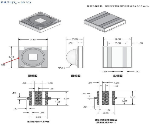
1. All dimensions are in millimetres. The tolerance is ± 0.3 mm unless otherwise stated.
2. Lead spacing is measured at the point where the leads emerge from the package.
3. The resin protruding from beneath the flange must not exceed 1.5 mm.
4. Specifications are subject to change without notice.
5. It is prohibited to drive LEDs without a heat sink.
6. It is strongly recommended that the temperature of the lead should not exceed 55oC.
7. The current must be derated appropriately to ensure that the junction temperature remains below the maximum.
8. LEDs are not designed to be driven in reverse bias.
|
Colour |
Radiometric Power (mW) |
Radiation Pattern |
|
| Minimal | Maximum | ||
| UV | 600 | 800 | Lambertian |
Optical Characteristics at 700 mA, TJ = 25 °C (1)
|
Peak Wavelength λp |
Spectral half-width (nm) Δ λ 1/2 |
Temperature Coefficient / Dominant Wavelength Δλ_D/ΔT_J (nm/°C) |
|||
| Colour | Min. | Typ. | Max. | ||
| UV | 395 | 400 | – | ||
● MaxLite maintains a tolerance of ± 1 nm for peak wavelength measurements.
|
Colour |
Radiation Pattern |
Total Included Angle θ 0.90 V (degrees) |
Viewing Angle 2 θ1/2 (degrees) |
Typical candela on axis (cd) |
| UV | Lambertian | 140 | 120 | – |
Electrical Characteristics at 700 mA, TJ = 25 °C
| Forward Voltage VF (V) |
Dynamic Resistance (Ω) |
Temperature Coefficient of VF (mV/°C) ΔVF/ΔTJ | Thermal Resistance from Junction to Slug (°C/W) | |||
| Colour | Min. | Max. | ||||
| UV | 3.4 | – | 4.0 | 1.0 | -2 | 10 |
Absolute Maximum Rating at a temperature of 25
| Parameter | Maximum Rating |
| Power Dissipation | 3W |
| Peak Forward Current (1/10 duty cycle, 0.1 ms)
Pulse Width) |
900 mA |
| Continuous Forward Current | 700 mA |
| Linear Derating from 30°C | 0.5 mA/°C |
| Reverse Voltage | 5V |
| Operating Temperature Range | -20℃ to +80℃ |
| Storage Temperature Range | -30℃ to +100℃ |
| Lead Soldering Temperature [1.6 mm (0.063″) from
[Body] |
350℃ for 5 seconds |
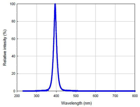
UV Colour Spectrum

UV light-emitting diode encapsulated in a quartz glass lens; 3535 UV lamp; narrow beam angle, high power.
Analysis of Advantages: Due to cost considerations on the part of packaging manufacturers, silicone lenses were initially adopted as the packaging material for LED chips on the market, and users have also widely adopted them for cost reasons.
LEDs with silicone lens encapsulation have encountered numerous issues during use, such as yellowing of the lens and widespread instances of lens detachment. Yellowing of the LED chip reduces light output and shortens its lifespan, whilst detachment of the silicone lens allows water vapour and airborne dust to enter, leading to short circuits and the LED failing. Currently, the narrowest beam angle for quartz glass lenses from overseas manufacturers is generally between 45 and 60 degrees; 30-degree lenses are rare. However, having mastered the encapsulation technology, we have launched a 30-degree quartz glass lens, offering a narrow 30-degree beam angle with a wide viewing angle. Hard quartz glass offers superior light transmittance and does not yellow. The ‘touch-top’ encapsulation process enhances airtightness, preventing detachment and thereby extending the service life of the UV LEDs. Importantly, the cost is no higher than that of silicone lens encapsulation, making it excellent value for money.